Tuesday 31 December 2013

Abstract DIP model - Part II


An abstract model for DIP came across my mind. It contains four sections viz; Acquire, Transfer, Display and Interpret. This post is second part of the series. Please refer earlier post (November 2013) for detailed introduction and to know about Acquire block.

Transfer Block:
It is in-between Acquire and Display block. As in Figure 1, input and output of Transfer block is digital data. It acts as a data compressor at the transmitting side and as a data expander at the receiving side (Display Block). This is because sending digital data without compression is a bad idea. Figure 1 describes a scenario. Here a person shoots an image using digital camera and transfers the image to hard disk in JPEG file format. Later it is opened and displayed on the computer screen. Here camera functions as acquire block as well as transmitter-side of Transfer Block. Computer functions as a receiver-side Transfer block as well as display block.
Figure 1 Digital Camera and Computer Interface
The transfer of digital data between Transfer Sub-blocks may occur through communication channel. This may be through wired (cables) or wireless medium. By nature all communication channels are noisy. It means that the data sent over the channel will be corrupted (1 becomes 0 or 0 becomes 1). A channel is considered good, if out of one million bits, one bit goes corrupt (1 out of 1000000). Various measures are taken to minimize or eliminate the impact of noise. Adding extra bits to detect as well as to correct the corrupt bits is one such measure. In CD and DVD Reed-Solomon Codes are extensively used. For further information search Google with the keyword “Channel Coding.” One may wonder when CD becomes a communication channel. Normally transfer of data from point 'A' to 'B' takes place via a channel and takes finite time (order of milliseconds). If the transfer of data takes near-infinite time then it can be considered as stored. Thus from this view point, transmission of data and storage (in CD or DVD) are functionally same.

Why compression?
The photons are converted into charge by image sensor. All the charges are read-out and they form a electrical signal. This analog signal is sampled and quantized to produce digital signal. Because of spatial sampling, resultant data is voluminous. Thus each image sensor's photon accumulation is represented in a pixel as a digital value.

Image is made up of rows and columns of pixels. The row and columns of data can be represented in matrix form. Programmers consider image as an array. Each pixel may require one bit to multi-bytes to represent digital data. A pixel from two coloured image (say black and white) requires only one bit to represent. A gray scale image uses 8 bits to represent shades of gray. Black and White TV images falls under this (Gray image) category. Colour image is composed of red, green and blue colour. Each colour shade requires 8 bits. Thus 24 bits (3 bytes) are required for each pixel. A HDTV size frame (image) possesses 1920 x 1080 pixels and requires 6075 KB (1920 x 1080 x 3) size storage. A one minute video requires 8900 MB (6075 KB*25*60). Thus half a minute video will gobble one DVD.  It requires 170 DVDs for single movie. One may wonder, how a entire Hollywood movie (nearly 90 to 100 minutes) is put inside a DVD. The answer is compression. The main objective of this example is to make ourselves to realize the mammoth data size of image.

Solution: Remove Redundancy 
There is a high amount of correlation exists between pixels in continuous tone images (typical image from digital camera). Thus one can guess a pixel value by knowing the values of neighbouring pixels. Put in another way the difference between a pixel and its neighbours will be very minimum. Engineers exploit this feature to compress a entire Hollywood movie into a DVD.  

Redundancy can be classified into interpixel redundancy, temporal redundancy and psychovisual redundancy. Temporal (time) redundancy exists in video only and not in image. Our eyes are very sensitive to gray scale variation than colour variation. This is an example for psychovisual redundancy.  By reducing redundancy high compression can be achieved. Transform coding converts the spatial domain signals (image) into spatial frequency domain signals. In the spatial frequency domain, first few coefficients contain large amplitude (value) and rest of the coefficients contains very small amplitude. In Figure 2, bar height represents the value. White colour bars represent the pixels and pink colour bars represent DCT coefficients. The real compression occurs by proper quantization of coefficient amplitude. The low frequency components i.e. first few coefficients are mildly quantized. The high-frequency coefficients i.e. rest of coefficients is severely quantized and outcome reaches near zero value. High frequency signals are highly attenuated (suppressed) but not eliminated. The feel of image crispness arises due to the presence of high spatial frequency components. Once high frequency signals are removed from an image become blurred. In JPEG, colour images are mapped into luminance and two chrominance layers  (YCbCr) and Cb and Cr layers (psychovisual) are highly quantized  to achieve high compression.

Figure 2 Spatial domain and Spatial Frequency domain. Courtesy [1] hdtvprimer.com
The quantized coefficients are coded using Variable Length Code (VLC) and then sent to receiver or put into storage device. In the VLC, highly occurring code is alloted with fewer bits and rarely occurring codes are alloted with more number of bits. Very good example for VLC is Morse code. Well known Save Our Souls (SOS) signal is represented as dot dot dot dash dash dash dot dot dot (...---...). In English language S and O are frequently occurring so they given shorter code. Less occurring letters like X, U will have longer code. Huffman code is a VLC, that provides very good compression.

In the receiver side VLC are decoded. The reverse operation of quantization occurs and transformed coefficients are again reconverted into spatial signals to produce the reconstructed image. Severity of quantization and file size are directly proportional. Image quality and quantization severity are indirectly proportional. The quantization makes an irrecoverable loss of signal i.e. it is impossible to recover original signal from quantized signal. For our eyes compressed JPEG image and the original image are practically indistinguishable.

Compression of images using quantization of spatial frequency coefficients is called lossy compression. This method is not permitted for medical images and scanned legal documents. Thus lossless compression is used. A image with 100 KB file size can be compressed into 5 KB file size using lossy compression. But with lossless compression one can achieve only 35 KB file size. Lossy and lossless compression is possible with JPEG. Advanced version of JPEG is JPEG2000. In the JPEG2000 Wavelet transform is used instead of Discrete Cosine Transform (DCT).

Spatial Domain Compression
 The transform coding poorly performs on cartoon images with limited colours and line art images. The exploitation of correlation can be carried out in spatial domain itself. VLC can be used to used to compress this sort of images. But underlying source probability of image is required for efficient compression. To overcome this problem dictionary codes are used. All ZIP compression application use dictionary coding. This coding method was developed by Limpel and Ziv in way back in 1977 and the method was named as LZ77. Next year, LZ78 arrived. Later Welsh modified LZ77 to make it much more efficient. It was named LZW. In 1980 Graphics Image Format (GIF) was introduced in Internet. It extensively used LZW. Few years later people come to know that LZW is a patented technique. This sent jittery among Web developers and users. Programmers came out with alternate image standard called Portable Network Graphics (PNG) to subdue GIF dominance. PNG uses LZ77 technique and patent free. In dictionary coding, encoders search for patterns and then patterns are coded. Longer the patterns better the compression. 

Knowledge on Information Theory is required to understand to evaluate various VLC. Information theory is an application of probability theory. What is information? If a man bites a dog then it is news. This is because chance of event occurrence is very low and instills interest to read. Put it in another way information value is very high. (Pl. don't confuse with computer scientist usage of information)
  Digital content duplication is a simple affair. So, content creators were forced find some ways and means to curb piracy. Digital Watermarking is one such solution to curb piracy. Here copyright information is stored inside the image. Presence of TV logo on television programmes is a very good example. Invisible watermarking schemes are also available. Steganography is a art of hiding text in images. Functionally digital watermarking and steganogragphy is similar but their objectives are totally different.

Note 
 The objective of this post to give overview of Transfer block. For more information please Google highlighted phrases.


Source

1. What is exactly atsc [Online]. Available http://www.hdtvprimer.com/issues/what_is_atsc.html
Saturday 30 November 2013

Abstract DIP model - Part I

A comprehensive all encompassing abstract model for Digital Image Processing (DIP) come across my mind. Let me put forth my thoughts in a lengthy manner to span several posts. This post is the first part of the series.

Introduction
Normally DIP is studied as a stand alone subject. Learners misunderstand the subject and associate it with compression, compression and compression. I personally feel it should be studied as “part of a whole.” Then only the real face of DIP can be perceived. My abstract model is an outcome of 'part of a whole' philosophy. As it lacks the academic rigour, model is not suited for scholarly publication. But model may be helpful to gain insights and dispel myths about DIP.
Engineers are expected make products to improve the quality of life of human beings. They are expected to use scientific knowledge in product making. The product are made in industry and sold in the market. The required level of knowledge about industry and market is not taught in the curriculum. This severely hampers engineers' thinking. Hard liners may counter argue in following way. “Part of whole thinking” will dilute engineering. If a student wants to learn about market, let him do an MBA.

The abstract model contains four sections viz.; Acquire, Transfer, Display and Interpret. In practice images are captured and then either stored or transferred. Later they are either printed on paper or shown on a screen and the images are interpreted by human brain with the help of eyes. What is new in this model is human brain is brought to the fore and not human eye. One may wonder, why human eye is not given the due credit or put in other way, why human brain's role in seeing is given undue importance in this model. Whether it is a sensational article written to draw more visitors? Please read the article further and I assure you all your anxieties will tend to cease. 

Acquire
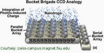
The responsibility of acquire section extends from acquiring reflected light from the subject that is shot till conversion of captured light into electrical signals. It has four subsections viz. Lens, Sensor, Read-out electronics and A-to-D converter. Lenses collect the light that is reflected from the subject and focus it on the sensor. Array of sensors ('n' rows x 'm' columns) are used to in camera to capture images. Number of sensors in the array and resolution of image is directly proportional. Sensors can be categorized into CMOS and CCD type. We all know numerous photons forms a light ray. Photon impinges on the sensor's photosite (i.e. light sensitive area), and the electrons in the valence band moves to conduction band. This causes flow of electrons and forms current in the sensor. This phenomenon is called photoelectric effect.  The stored charges in the sensors can be treated as tiny capacitors (we know junction capacitance in diode can be treated as capacitor).  In a sensor, only 40 % of area is covered by photosensitive material. Remaining area is filled with amplifiers and noise reduction circuits [1]. The charge stored in tiny capacitors (actually sensors are built using MOS transistor), has to be read out before they get discharged (similar to working of dynamic RAM). Faster reading-out is required for higher resolution images. Then read-out voltage signals are amplified and converted into digital signals (or data). I guess higher the resolution leads to lesser the A-to-D conversion time pixel.  For detail discussion refer [2], [3]. Figure 1 beautifully explains the concept of read-out [3]. Line sensor arrays (1 x m) are used in photocopying (Xerox) machines. Here a stick that contains row of sensors moves from top of the page to the bottom of the page to collect the pixel information. In thermal systems only single pixel sensors (1 x 1) are available.

Figure 1. Photon collection by photosite and read-out 

The above paragraph would have provided the functioning of light capturing in a superfluous way. Technical details are trimmed to minimum level so as to highlight the principle of light capture. Knowledge on optics and machining is very important to fabricate lenses. The power of DSLR camera hinges on powerful lenses. Good knowledge on micro electronics is absolutely essential to understand the functioning of sensor, read-out amplifier and A-to-D converter. To design and fabricate reasonable good resolution acquiring subsystem, a sound knowledge on Very Large Scale Integration (VLSI) and knowledge on related software tools are essential. In reality subjects like optics, microelectronics and VLSI are taught even without veiled referenced to camera or scanner systems. 

     The technology has reached to such a stage that even entry level camera (low priced camera) is capable of taking 10 Mega pixel resolution images. When film based camera reigned, photography was a costly hobby. So very few bought the camera. To acquire digital colour image requires three filters namely red, green, and blue. Use of three filters is costly and instead single sensors are used to cut down the cost. For that 'Bayer Patterns' are used. When Bedaprata Pain [4] and his team developed affordable CMOS active pixel sensor, digital camera become affordable and today every mobile phone is embedded with a camera.  

Product Market
The next level of innovation will be in improving usability of camera and not in cost cutting. As the cost comes down heavily quantum of profit will also comes down. To maintain the profit industries go in for volume. Let Camera Company named ABC sells 1000 camera for the price of Rs. 5000. Let the profit be Rs. 500. The net profit is Rs. 5,00,000 (1000 camera x Rs 500). If the same company sells 10000 camera for the price of Rs. 3000 then the net profit is Rs 30,00,000  (10000 camera x Rs 300 as profit). Profit has increased many folds. This logic go well until everyone acquires a camera. After that ABC has find innovative ways to keep the net profit same. 

The ultimate aim of the camera manufacturing companies can be put in this way “even a moron should take pictures like a professional photographer.” As we all know we have huge number of amateurs and very few good photographers. The improve the market size of costly DSLR (Digital Single Lens Reflex) camera, industries should target the huge amateur base. But general public neither have patience nor time to become like a professional. To bridge the skill gap lot of intelligence is added in the camera. 

Market need satisfying algorithms
Face detection algorithms are used to help to shoot proper pictures by amateurs. Earlier this feature was available in point-and-shoot cameras. Nowadays this feature is extended to professional models like DSLR cameras.  Most of us, are unable to set proper ISO, aperture and shutter speed for the required shot. That is why auto-focus and auto-lighting cameras sprung up. But there is a lot scope for improvement in these cameras. Next, amateurs' hands are not stable at the time of taking shot and invariably it results in shaky pictures. This can be corrected by using “image restoration” class of image processing algorithms. Sometimes enough lighting may not be available at the time of shooting or extraneous light may fall on the subject. These errors can be partially corrected using image editing softwares like Photoshop and GIMP. Photoshop is the most popular commercial image editing software and GIMP (GNU Image Manipulation Program) is a open and free software. Lot of image processing algorithms will be deployed in ensuing intelligent camera. 

Source
1. How Digital Cameras Work, [Available Online], http://www.astropix.com/HTML/I_ASTROP/HOW.HTM
2. Digital Processing Techniques, [Available Online], http://www.astropix.com/HTML/J_DIGIT/TOC_DIG.HTM
3. ZEISS Microscopy Online Campus | Microscopy Basics | Understanding Digital Imaging, [Available Online], http://zeiss-campus.magnet.fsu.edu/articles/basics/digitalimaging.html
4. Bedabrata Pain - Wikipedia, the free encyclopedia. [Available Online], http://en.wikipedia.org/wiki/Bedabrata_Pain


Thursday 31 October 2013

Television and Movies – Visual Fast Food?

Everyday we encounter lot of pictures. Pictures appear in television, cinema, newspaper, magazine or the Web.   Pictures are used to convey emotions and messages. Except a few, most of us take things for granted and spend our scarce resource (thinking) on odd or rare events. For example until Sir Isaac Newton, the falling of apple from a tree was considered the norm and people simply consumed the fallen apple.  Likewise viewing pictures are taken as a very usual thing and we skirt to think about it. In this post, the discussion will be on the “Role of pictures in our life.”

It will better to define first and then get into the essay. Pictures can be classified eye-captured pictures, device-captured pictures and synthetic picture. If I physically visit the Amazon jungle and enjoy the beauty through my own eyes then I call it eye-captured picture. If I see the Niagara Falls in a movie or television or magazine then I call it as device-captured picture. A picture that is created by artistic rendition with or without computers is called as synthetic picture. 
Two hundred years back pictures mean almost eye-captured pictures only. Rich people only had the opportunity to own synthetic pictures (paintings). Commoners who live in big cities like Rome would have enjoyed the Michelangelo paintings in the ceiling of the Sistine Chapel. Colour photograph started appearing after 1861. It helped to capture portrait of a person or natural landscape with less effort and time. Earlier times painters performed this task. Thus human painter was substituted by colour camera. But it was no way an easy task produce multiple copies. First colour illustrations appeared in newspaper in 1934 in UK. To have a glimpse of old colour photographs refer [1]. Colour television emerged in the year 1960 in USA. After 1980 World started seeing lot of device-captured pictures. I can fairly assume everyone see TV for two hours per day. The amount of pictures in print medium (newspaper, magazine) is relatively less. On the Web, picture is more than print medium but lesser than the TV.  Let us conclude in a day average device-captured pictures viewed is for two and half hours (two hour tv plus half an hour Web and print). Within a span of two hundred years, the time spent on device-captured pictures rose from near zero to 150 minutes.

A cursory glance of  “150 minutes of device-captured picture viewing” looks like a trivia. At most it may amuse people and make people feel proud of technological superiority. Broadcast media (TV and movie) is a medium that transcends the distance. For example seeing a war, seeing piranha fish present in Amazon rivers, and seeing skiing in Alps mountain range with naked eye is a rarity for a common man living in India. Thus one is able to have a near real experience in battle field, jungles and sky scrapers without moving from their physical place. 

A coin has two sides. Likewise the ability to “transcend distance and take part important events in world” has profound positive and negative effects. Without picture, visualizing Amazon jungle with textual description is nearly impossible. Our knowledge has tremendously increased with the rise of access to pictures. People in India know very well about US President Barack Obama, Osama bin Laden, Bruce Lee, Hollywood celebrities, Kangaroo, Niagara Falls, and Eiffel Tower all because of pictures. Learning medicine, architecture, archaeology and many fields become easier because of availability of pictures. Forensic experts are able to identify criminals without physically visiting the crime spot. Surveillance camera captured pictures which help us to prevent crime as well as to capture the criminals. 

The negative sides are “we are conditioned to see what we want to see” and the gap between device-captured and eye-captured pictures is very high. When viewing a TV and movie, we see the world through the eyes of content creator (director of movie). In one sense our freedom is lost. As watching movies acts as a medium of escape, we voluntarily subject our-self for loss of freedom. Thus it becomes easy to mass brain-wash the so called modern man than their ancestors. Next, a person in India via TV can live in America for few hours per day. So the distinction between real and reel shrinks and confuses person's thinking ability.
The important point is we see extremes in device-captured images. First principle of journalism states that “If a dog bites a man then it is not news and if a human bites a dog then it is news.” Mathematically it means lower the probability of occurrence, higher the probability to be published. That is why we see six-pack males like Arnold Schwarzenegger and Sylvester Stallone, handsome Leonardo DiCaprio and beautiful hour-glass females. Fig.1 contains the still from the movie Titanic and it is very romantic. Seeing this kind of romantic encounters with naked eye is almost impossibility. Thus for 150 minutes we see what is not possible to see with naked eye.

Figure 1. A romantic scene from the movie Titanic     Courtesy: Internet  
Studies have established long hours of TV viewing affects children's ability to learn, their retention capability and socializing skills. The impact of camera-captured pictures in humans has to be documented with scientific data. Seeing a picture is not an independent task of eye alone. It is an outcome of close coordination between eye and brain. Thus it will be better to say “We Perceive” than “We See.” When we encounter optical illusions our brain fails to interpret the incoming visual signal from the eye properly. When ever meditation or prayer is performed, we normally close our eyes. This helps us to cut down the distraction as well as reduce the work load of brain. Seeing something actually makes our brain to give priority to process on the incoming visual signal. That is why when we sit in a park or watching TV makes us to feel as if we are getting rid of our problems. Actually, the brain starts to process visual signals rather than pondering on the problem. 

We have a high intake of processed food (fast food) compared to our ancestors. Wide spread prevalence of life style diseases like diabetes, obesity are linked to processed food. Similar in lines we have high intake of camera-captured pictures compared to our ancestors. Will it creates any problem for us?

Before we wind up we will have quick recap of what we have discussed in this post.

  • Eye-captured, Camera-captured and Synthetic pictures
  • Camera-captured images are different from eye-captured pictures
  • Camera-captured picture from 18th century, transcends distance, captures extreme events
  • Amount of camera-captured pictures is 150 minute per day and 200 years back almost zero minutes.
  • With camera-captured images voluntary brain-washing is carried out.
  • Cognitive load on brain due to camera-captured pictures is high.
  • Camera-captured picture = Fast food 

Source
1.  Colour images from 1930s unveiled – Daily Record [Available Online] http://www.dailyrecord.co.uk/news/scottish-news/colour-images-from-1930s-unveiled-1276428

Acknowledgement
 Grammatical correction was carried out by a final year engineering student.

Sunday 29 September 2013

Second Avatar of Stereoscopy


     Recently I was watching a promotional video of palatial hotel from YouTube video server. That video clip had 3D viewing option. It stirred my curiosity and selected the option. All I was able to see was a blurred video as I did not possess required 3D glass. I searched in Google and I found that YouTube automatically converts short video clips that have a resolution of 1080p (1920 x 1080 progressive mode) from 2012 onwards [1]. If I had watched with 3D glass I would have virtually visited the hotel rather than seeing. Depth perceivable in 3D creates a new experience. The right technical word for 3D movie is stereographic movie.

   The YouTube video clip made me nostalgic. My first stereoscopic experience was way back in 1984. As a boy I had an opportunity to view “My Dear Kuttichaathan” (in Tamil language 'kutti' means small, 'chathan' means shaitan or genie) movie. Exhibitors collected extra fee for 3D glasses and at the end of the movie they got back the eye glass. I was really shocked when arrows from silver screen tried to poke my eyes and pleasantly surprised when bunch of roses and cone ice-cream popped out of screen. No doubt the movie was a block buster. After a gap of 25 years I watched a 3D movie. It was none other than James Cameron's Avatar movie and my children were my fellow viewers. My children enjoyed to the core. I liked the theme of the movie but the 3D effects did not create an 'awe' in me. I realized I have become old. 

    After 'My Dear Kuttichaathan' few 3D movies came to tap the emerging 3D market. I saw one or two. I was not impressed and public too shared my opinion. Slowly 3D popularity declined. Production cost of stereographic movies were high compared to normal movies and production work-flow has to be modified to suit 3D movies [2]. Stereographic movies required two projectors instead of one and both of them have to be synchronized. Directors were not able to effectively use the 'depth' to convey their story to audience. Consumers required to wear an eyeglass and safe return of the eyeglass was their duty. Whole lot of extra efforts among stake holders for few pop-ups was not worthy. After a lull period of 25 years Avatar movie created the frenzy. One may be perplexed why there was a long gap of quarter century and why there is a 3D frenzy now? Answers to these questions will come out when we dwell into past and do some reasoning.

     As for as India is concerned before the color TV penetration, 'movie going' was the prime pass time activity. Entire family went to movie halls and films are also produced to cater the needs of entire family. In late 1990s TV and satellite broadcasting glued the family to the drawing room. Youth (15 to 30 years of age) become major customer base for films. Automatically movie content were made to suit the audience. Youngsters like stunning visuals. Thus 3D become a apt to tool to make youth to come to theatres.

    The next threat for theatre came in the form of VCD (Video Compact Disk). Prior to VCD Video Home Systems (VHS) was the norm. It used magnetic tape to store the analogue signals. VHS player had lot of mechanical components and regular maintenance was required. Copying from Master tape to another was cumbersome. The quality of copied content quality were inferior to the Master. Thus piracy was kept at a bay. Thus VHS never challenged the dominance of theatres. In contrast, the VCD carried digital signals and VCD player had more electronics and less mechanical components. As VCD market expanded prices of VCD player started falling. Pirated VCD making was a simple task. Thus just released movies were available in pirated VCD and family watched in their television. This was death blow to theater owners and in turn to movie industry.

  The VCD threat was countered by producing movies with spectacular visuals (ex. Matrix movie fight scenes were talk of the down) and with surround sound systems like Dolby. This discouraged movie patrons to view movies on their Television sets. Stereoscopy produces stunning visuals to draw the crowd to the theatres and curtails piracy.
 
A still from the movie 'Avatar'
    Avatar movie grossed box office collection of two billion dollars, which is a huge sum in even in Hollywood [3]. Right technology and sizable market emerged in late 2000 and arrival of Avatar movie ushered a new chapter in stereoscopic movie industry. Cinema producers realized 3D is a untapped potential and started releasing animation movies. The number of 3D theaters started exploding after 2000. In the year 2007 it was 1300, in the year 2009 it reached 9000 and at present 45000. Most of the theaters are constructed in China. In the year 2005 Hollywood produced only five 3D movies, in 2009 it was 20 and in 2012 it almost doubled [4]. In the year 2012, out of 15 highest-grossing films nine were stereoscopic movies. Quarter of the revenue is generated from USA and three quarters comes from rest of the world. Rising economies like China, India contributes a lot. As movie industry falls under 'high risk – high reward' category and 3D technology becomes a safe bet.

Seven reasons for rise for 3D
  1. It introduces a illusion of depth which produces a new experience. In normal movies shadow acts as surrogate for depth.
  2. It suits well with youngsters, who prefer stunning visuals than a emotional roller-coaster. Next they are experience conscious. So price is not a barrier.
  3. Amount of money grossed from a stereoscopic movie is huge. The failure rate is less. Thus 3D movie is a safe bet for film producers.
  4. Cost of stereoscopic movie ticket is 30 percent higher than normal movies. This makes a hole in movie patrons but helps theatre owners to fill their coffers.
  5. Stereoscopic movies curtails piracy.
  6. Digital projection technology go well with 3D movies.
  7. Digital production is very cost effective for  3D movies.
Problems with 3D
    Film is a visual art that helps to tell a story. A good story will make the audience get hooked to the characters of the movie. That is why classical movies like Ben Hur, Five Men Army, Mackenna's Gold and Bridge on the river Kwai are still touches our hearts. A good movie should have a judicious mix of stunning visuals and emotions (ex. valour, sacrifice). Yesteryear directors were not sure of 3D medium's effectiveness in story telling and simply avoided the medium.

     Sometimes the presence of depth of field may become a source of distraction. For example in nude photography, there are photographers who still use B&W (Black and White) film stock instead of colour film stock. They claim B&W medium helps to appreciate the shape of female body. The faithful reproduction of flesh tone by color film really distracts the viewers and photographers are unable to convey their intention. Once visual effects artist commented in a public meeting that “When Science gets in Art goes out (from movies)”. Over indulgence on technology may actually spoil story telling capability.

    3D movies favours themes that are based on mythology, magic (ex. Harry Potter), adult, horror and cartoons. Thus movie goers are transported away from reality for 90 minutes. Thus 3D can be regarded as entertainment medium than a visual art medium.

     Our eyes has to focus properly on screen to feel the depth. Those who fail to focus get head ache and other related ailments. Visual discomfort and visual fatigue are studied extensively by scientists to improve the 3D movie going experience [5].

Summary
  1. It is a visual rich medium and toning down may be necessary to tell a story compelling way.
  2. It is genre limited. It is well suited for mythology, magic, horror and cartoons.
  3. Visual fatigue and visual discomfort has to be studied well for wide acceptance among public.  
Source
[1] Official Blog: How we’re making even more 3D video available on YouTube [Online] http://youtube-global.blogspot.in/2012/04/how-were-making-even-more-3d-video.html
[2] Casting a magic spell, [Online] http://www.thehindu.com/thehindu/mp/2003/05/15/stories /2003051500260100.htm
[3] Avatar (2009 film) - Wikipedia, the free encyclopedia, [Online] http://en.wikipedia.org/wiki/Avatar_(2009_film)
[4] 3 Signs That 3D Movies Are The Way Of The Future | Business Insider India [Online] http://readbi.in/st9nJY
[5] M. Lambooij and W. IJsselsteijn , “Visual Discomfort and Visual Fatigue of Stereoscopic Displays: A Review,” Journal of Imaging Science and Technology, vol. 53, no. 3 pp. 030201–030201-14, Mar. 2009. [Download]
http://www.cs.sfu.ca/CourseCentral/820/li/material/source/papers/Visual-discomfort-09.pdf

Saturday 31 August 2013

Status of DIP in India and possible remedies

        In this post, problems faced by Digital Image Processing (DIP) field in Indian academia is discussed.  Potential of DIP is highlighted and  underlying strength is discussed. Measures that has to be taken to achieve the potential is presented.

I. Problems
  1. First and foremost weakness is prevailing misconceptions about the field.  They are listed as follows
    • Bible for DIP is written by Gonzalez (Rafael C. Gonzalez and Richard E. Woods, Digital Image Processing, 2nd edition, 2002) and the book had more emphasis on mathematics. In recent editions, maths content was gradually reduced to make it convenient to computer science students also. Thus  phrase like “DIP is nothing but two dimensional spacial signal processing,” makes most of the people amused.
    • Most of the faculty and students have a notion that DIP is all about compression, compression and compression. I don't know how this notion crept into academic community. If some one say I am doing my research on image processing then next question will be “whether you are working on image compression?”
    • Academia has no qualms to associate Digital Signal Processing (DSP) subject (In American parlance - course) with mathematics. It is adjudged as a core electrical engineering subject. But 2D signal processing ie. DIP is not associated with maths and offered as elective course. What a pity.
  2. The next important weakness is, there are only handful people who really know DIP. To score good marks in examination with minimal effort, DIP is the best option. But one has to struggle more hard to become an expert.  The reason is very simple. One has to get out of the  prevailing misconceptions trap.
  3. There is a small pool of DIP experts only exist. Thus they nearly face no competition and there is no incentive for them to  improve their knowledge.
  4.  Most of the professors in engineering colleges are from communication, networks, and vlsi background.  Almost all bright students prefer to work under a professor for their project work. Thus best talent are not available to DIP field.
  5. In most of the engineering colleges in India, DIP is offered as an elective subject (In American parlance - course). It is studied in last semester B.E. or B.Tech. programme. Thus students loose an opportunity to do project in DIP. Even if they do a project, they lack the theoretical foundation. It results in low grades or marks and DIP field is falsely branded “unfit."
II. Potential
  • There are really very few experts are there. So there is enough vacuum is there, that needs to be filled. Put it poetically “DIP is less trodden path.” It is difficult to travel but rich dividend is waiting makes worthwhile to walk alone.
  • DIP applications are innumerable. So one can establish their expertise on any one of the applications.
III. Strengths
  1. A Internet enabled laptop with MATLAB can act as a Lab. So every electronics engineering student can own a DIP lab.
  2. Good amount of information is available in Internet. So one can download codes and run on their systems to understand the concepts.
  3. Outcome of DIP is an image. So one can implement their methods / algorithms on computers. As one can have actual result, it really improves the confidence as well as self esteem. In areas like communication, networks and vlsi they have to be contented with simulations. They are supposed to work in labs of  premier institutes to come out with actual result (ex.  a integrated chip).
  4. International journal “Transactions on Image Processing” is published from IEEE (Institute of  Electrical and Electronics Engineers) association. The USA based IEEE association is the largest and most respected electrical engineering association in the world. Impact factor of transactions on image processing is more than three (3.199). This is a very high score for a engineering journal.  This means there is huge scope and impact on society in doing research in image processing.
  5. The cost of cameras, scanners, computing hardware and displays are coming down. Thus  inspection systems (Biscuit, rice etc), activity detection systems  can be built with low cost. This will create a huge market for new products and work flows.

IV. Improvements
  1. People working in Image processing should come together and they have to work in tandem for the welfare of DIP. This in turn will help them to grow. One may think why cant start an association? Yes, nice idea. But due to Indian mindset, office bearers and members will spend much time on playing politics than doing something for DIP.
  2. In the universities DIP has to be given due importance.
  3. DIP awareness camps has to be organized by institutions. So as to make popular among students.
  4. Motivated youngsters are the need of the hour to build research capability and  to involve in DIP promoting activity. The prime objective of young researchers should be doing research and not acquiring PhD degree.
  5. Free access to quality content. For example a wikipedia for DIP (dIPedia).
  6. A trainer kit has to developed or popularized, which permits to do image processing applications on embedded systems.
  7. If smart phone image processing trainer kits (Android, Symbian, and Windows mobile based) made available then students will come out with beautiful applications. For example a smart phone app (application or executable program) is written to detect presence of diseases in agriculture farms and suggest remedies.  Next, If someone hovers the smart phone on unknown plant then the app  can come out with the botanical name and local name. These apps can be  greatly helpful to public as well as DIP researchers.

After reading this post, some may wonder what is my contribution to DIP?   Answer is 'not much'. This post is culmination my thoughts and few failed activities. Earlier I started a website especially for image processing. Due to various reasons I was not able to carry out regular updates and finally it  failed.  Then I started this blog to bring out information that are not covered in the typical textbooks.

Wednesday 31 July 2013

Inside Thermal Imaging Camera

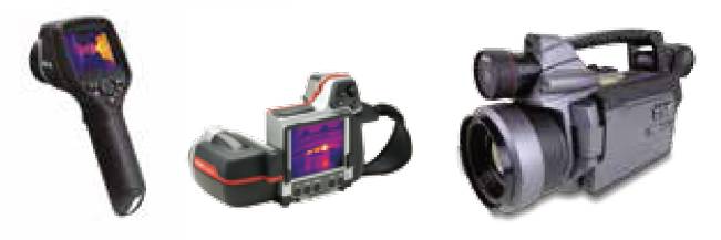
     This post deals about components of infrared camera system. Infrared region ranges from 0.7 μm to 1000 μm. For convenience infrared is split into shortwave (3 to 5 μm) and longwave (8 to 12 μm) bands [1].  Few types of thermal camera are shown in Figure 1. Their appearance will be similar to conventional cameras.                                 

Figure 1. Various types of Thermal Imaging Cameras Courtesy ref. [3]
In ambient temperature, radiant flux emitted by is more in longwave than shortwave. But shortwave is more sensitive to longwave at ambient temperature conditions. Sun radiation is small but significant in shortwave range. It is helpful to increase image contrast in some cases and in cases like measuring temperature of an object, sun radiation is unwanted. Longer wavelength can penetrate mist and smoke better than shortwave. So longwave always preferred in surveillance applications.

            At cursory level, architecture of thermal cameras will be similar to conventional cameras. The main differences are presence of scanning subsystem and cooling subsystem.  The schematic diagram is shown in Figure 2. The IR rays from object are focused on detector or detector array through IR lens. In detector IR to electrical signal conversion takes place. Readout circuits transfer the electrical signals to storage devices and display devices.

(i) Lens: Functionally Infrared and visible range lenses are same i.e. they perform same duty irrespective of the spectrum in which they operate. But Infrared lens materials have relatively higher refractive index than visible spectrum lens. For example germanium has refractive index of 4.01 at 10 mm compared glass which is having a refractive index of 1.5 at optical spectrum.

(ii) Scanning system:  This subsystem is missing in conventional cameras. Purpose of the scanning is to transfer image formed in the lens to the detector or detector array in well controlled fashion. The types of scanning systems are as follows; object space scanner, image space scanner, and afocal scanner. For detailed information refer [2].

(iii) Detector: It is the most important component in the entire thermal camera. Thermal detector and photon detector are the two types of detectors. In thermal detector, IR radiation heats the detector element and this in turn change in physical characteristics (for example, electrical polarization or resistance). This change in characteristics is measured.
In photon detector, electron absorbs the photon that comes from IR radiation and the electron jumps form one quantum level to another. It is more sensitive than thermal detectors. To have better performance quantum detector has to be cooled. This facilitates photons–electron interaction. Photon detectors are constructed using semiconductors. Either they act as photoconductors or photovoltaic devices. In photoconductor absorbed photons moves a valence band electron into conduction band and there by increasing the conductivity of device. As name suggests absorbed photon generates voltage in the p-n junction.  Shortwave detectors need to be cooled up to 195K but long wave has to be cooled up to 77 K.  This is the temperature of liquid nitrogen. (I strongly believe liquid nitrogen it is flammable)
They are mainly three types of photon detectors are available.
  • (a) Cadmium mercury telluride (CMT): By changing the composition it can be made to operate in longwave or shortwave band.
  • (b) Indium antimonide (InSb): It is used in shortwave band only. It can be constructed to operate as photovoltaic device or photoconductive device. For get best performance it has to be operated in liquid nitrogen temperature.
  • (c) Platinum Silicide (PtSi): This detector functions as Schottky barrier photodiode. It works in shortwave but with 77K temperature. It has very poor quantum efficiency. Only two percentage of incident photons are converted. It is well suited for arrays only. This material is well compatible with the readout circuit.

(iv) Detector Arrays:  Development of thermal arrays is relatively recent and possible as a result of MEMS(micro-electromechanical systems) technology.
  • (a) Pyrovidicon: This can effectively function in longwave band. Now this imaging device has become an historical interest. It functions similar vidicon video camera. But the detector is infrared sensitive.
  • (b) Resistive bolometer arrays: This is very popular array structure. Here temperature is proportional to change in resistance. It is made of top temperature sensitive resistive layer and bottom layer that contains read-out circuit. These two layers are connected by pillars. The air gap between two layers acts as a thermal insulator. These types of bolometers incorporate coolers to maintain an optimum temperature that is conducive to resistive element and the readout electronics.
  • (c) Ferroelectric/pyroelectric arrays: Construction-wise it is similar to resistive bolometer arrays, except the detection is based the pyroelectric or ferroelectric effect. Pyroelectric material become electrically polarized when there is change in temperature. This in turn generates charges and resistance of the top layer (resistive layer) goes down. A typical example for pyroelectic material is trigycine sulfate (TGS).
  • (d) Bimetallic Cantilever Arrays:  It has two layers and both of them hinges on capacitance measuring circuit as in Figure 2. Top layer is made up of gold bimetal and consists of IR sensitive film. This layer is supported by SiO substrate. Top layer and bottom layer is separated by air gap. As both layers are metal and in between air is insulator it forms a capacitor. When infrared falls on the film, top layer bends towards the bottom layer. This change of physical arrangement causes capacitance to vary. This variation is measured.


  • Staring array configuration: Thermal sensitivity of an imager can be improved if the effective imaging areas of the detector elements are increased. (Please note entire area of the detector is not occupied by imaging section of detector element. For example, in the bimetallic cantilever array only small portion of top cantilever is filled with IR sensitive film). Size of the detector elements must be limited to maximize spatial resolution of detector arrays. Various configurations are proposed and adopted in cameras, out of which staring array is very popular and deployed extensively [2].

(v) Cooling subsystems:
Most of thermal cameras employ cooling or temperature control for optimal performance. There are four types of cooling methods are used widely.
  • (a) Bulk cooling: It is the simplest cooling method. Here detector is placed inside the Dewar (Flasks ?) and later is filled with liquefied nitrogen. It is well suited for laboratory purposes.
  • (b) Thermoelectic cooler (Peltier cooler):  It is based on Seeback or Peltier effect. Current flowing through a junction of two dissimilar materials produces a change in temperature at junction. Direction of current flow decides whether the junction to be cool or hot. With this arrangement temperature up to -40K is achieved.
  • Other two coolers are Joule –Thomson cooler and Stirling engine coolers.

(vi) Processing Electronics and Display:
The generated voltage or current has to be read out, conditioned (amplified and A to D converted) and stored in a memory. Major problem is making an electrical connection to each and every detector element. To reduce number of external connections, on-chip signal processing has to be carried out. This strategy is already employed in CMOS and CCD arrays.  Maximum resolution of thermal cameras will be 300x300. So LCD displays will be very sufficient.

Source:
  1. IR Thermography Primer, FLIR Systems Co. Ltd, http://www.termogram.cz/pdf/thermography_primer.pdf, (749 KB, PDF)
  2.  Thomas L. Williams, Thermal Imaging Cameras: Characteristics and Performance. CRC Press, 2009.
  3. Thermal imaging guidebook for industrial applications, FLIR Systems AB,  http://www.flirmedia.com/MMC/THG/Brochures/T820264/T820264_EN.pdf  (2014 KB, PDF).


Sunday 30 June 2013

Thermal Imaging - I

Infrared is a range of electromagnetic waves that lies just below visible spectrum and above the microwave spectrum. As it lies below the red colour, it got its name. Wavelength of these rays ranges from 700 nm to 1000 micrometer. Like visible light these rays can be emitted, reflected and absorbed. These rays cannot be seen but it can be felt as our skin is sensitive to temperature. Any object that is above -273.15 degree Celsius or 0 degree Kelvin can act as a source of infrared radiation. That means an ice cube that is cold will also emit infrared radiation. Sir Frederick William Herschel discovered existence of infrared in the year 1800, when he was studying radiations from Sun. In 1900 Max Planck gave the governing laws behind the thermal radiation. For convenience infrared is split into shortwave (3 to 5 micrometer) and longwave (8 to 12 micrometer) [1].

In 1970 commercial grade thermal camera arrived for market. These cameras were bulky with several components. They required liquid nitrogen to cool the system. Typical example for this type camera is AGA Thermovision 660 [2]. Within 10 years size of camera reduced considerably. Now uncooled micro bolometer based infrared cameras are available. They look like visible camera i.e. conventional digital camera.

As for as working of thermal camera is concerned, is very similar to visible cameras. Infrared camera optics is focused on an object-of-interest and its heat signals are captured by detector. The detector is read row-wise and outputs are got in the form of voltage. Then A-to-D converters map the voltages into numbers. As infrared is invisible they don’t have inherent colour. So, false colours used and they are mapped to the data range to produce a thermal image. This is shown in LCD screen that is present in the camera. These images can be stored in memory cards.

Dissimilarities
  1. First is pixel count. A low end camera will contain 4 million pixels as compared to high end thermal camera that may contain 3 lakh (0.3 million) pixels. 
  2. A low end thermal cameras cost around $6000 US dollars [3] or 3 lakhs Indian rupees.
  3. Primary objective of thermal camera is to measure heat and record from every point of the object. Professionals are required to take a useful thermal image. They are expected to know the physics behind the thermal imaging and should have the ability to interpret the thermal images properly. Put in simpler terms it is a measurement tool. In contrast digital cameras are used to freeze important moments in life. So visible cameras are designed to be operated by everyone and shoot pictures with ease.
  4. A thermal image is always accompanied with visible picture. As thermal image is radiometric one, it should be always accompanied by a temperature scale (a bar that contains the colours used in the image along with corresponding temperature. This can be seen in Figure 2 thermal image). Thermal fusion images are optional but they are very informative. Please refer figure 1. For more images refer [1, 2].
  5. Infrared images use, false colour palettes like gray rainbow, iron. 

Night vision camera and infrared thermometer are sounds similar to infrared camera. Night vision camera requires very minimum visible light (moon light) and near infrared to capture image. A novice will mistook output of night vision camera as from infrared camera. Figure 2 will help to understand the difference. Infrared thermometer will capture temperature of particular spot i.e. pixel resolution is one pixel only. Any low end infrared thermal cameras will posses 3600 pixel resolution. 

Figure 2. Difference between visible, night vision and thermal infrared images
Applications
Few important applications of thermal imaging are electrical installations, machineries, thermal insulation inspections in buildings as well as in heat conducting pipes and flare detection. Thermal images can be used in medical diagnostics also. It is mainly used to detect breast cancer tissues. Thermal images are used to visualize the level of injury in the body. Medical related thermal images will not be discussed in this post. Refer [4] for other areas applications like sports, veterinary, music and dance.

Thermal cameras are primarily used as non-invasive testing equipments. Non-invasive testing is very popular for two reasons. It can be used in preventive maintenance and is very economical. Today all the machineries present in factories run 24x7 and throughout the year almost without break to produce cost effective products. Wear and tear and associated failure is natural in any machinery. Problem of occurrence of failure is avoided with preventive maintenance.

Greatest beneficiary of thermal imaging is inspection of electrical systems. They are classified into high-voltage installations and low-voltage systems. First generation thermal cameras were primarily used to inspect high voltage power lines. Corrosion in electrical connections in high-voltage installations increases resistance. This causes rapid rise in temperature and subsequent meltdown or breakdown of connections. Outcome of this will be unplanned outages and fire hazard. Electrical short-circuit is a major cause of fire in buildings, factories and godowns. Fires destroy materials worth of billion dollars in a year. 

It is a common knowledge, when a moving part in equipment is misaligned or malfunctioning then it will produce heat, later it manifest itself in excess vibration and in extreme condition it produces sound. As the first symptom of malfunction i.e. rise of temperature cannot be detected by conventional means, we rely on secondary symptoms like vibration or sound. For example, in mechanical systems like conveyor belts worn out of rollers can be easily detected using thermal imaging. Some of the problems like motor failures due to brush contact-wear and armature shorts produce excess heat only. They go undetected by vibration analysis.


Building inspection: Western countries reel under severe winter and to make life comfortable houses use central heating systems. If walls and windows of the building are properly insulated then heat will seep through them. At summer, places like in Middle East and India will reel under excess heat. To combat this centralized air-conditioning systems are used. If the house is not properly insulated then heat will seep through walls and reduce the efficiency of cooling system. Thus thermal images of house are used to find out insulation efficiency of house. Properly insulated houses require less energy to cool or warm them. Thus it leads to lot of savings. Same holds good for pipes that conduct steam and cold liquids. 

Infrared camera fitted with protective filters can see through flames. This helps a lot for fire fighters to look beyond flames and take appropriate rescue operation. In certain industries like petroleum refineries harmful gasses are generated and they should be burned off in flares to avoid environmental degradation. Normally these gasses are invisible to naked eye. Thermal images of chimney will show whether gasses burned or not.

The last but not the least application is to teach physics. The interaction between walking person shoes with floor can be captured in thermal camera in video mode. The footage will help students to see the frictional force and visualize its effects. A basketball that falls on the floor will get deformed for brief moment and its temperature will rise. A high-speed thermal video footage will help student to see rather than to believe teachers’ lecture [4]. 

Note
o Ref. 1 contains 28 pages. It is very interesting to read and has good amount of illustrations to convey concepts. 
o Please search for thermal image videos in youtube.  I hope it will really help us.

Source

1. IR Thermography Primer, FLIR Systems Co. Ltd, http://www.termogram.cz/pdf/thermography_primer.pdf, (749 KB, PDF)
2. Thermal imaging guidebook for industrial applications, FLIR Systems AB, http://www.flirmedia.com/MMC/THG/Brochures/T820264/T820264_EN.pdf, (2014 KB, PDF)
3. B.R. Lyon Jr., R.J. Rogers, Techniques, “Tips and Tricks: Operating a Modern Radiometric Thermal Imaging Camera,” Presentation handout of ASNT 2007 Fall Conference, Las Vegas, USA, Nov. 14, 2007. 
4. M. Vollmer and Klaus-Peter Möllmann, Infrared Thermal Imaging: Fundamentals, Research and Applications, Wiley-VCH Verlag GmbH & Co., Germany 2010.


Thursday 30 May 2013

Digital Cinema Projection Technologies

         Digital Cinema projectors are the last and most important component in the Digital Cinema system. In the 100 year history of cinema lot of advances came through in cameras, lenses, widescreen movies, audio and so on. But projectors remained unchanged for very long time. “Star Wars” movie was a trend setter. It was shot in digital camera and it was projected using digital projectors [1]. This was a real break through.  In the world there are around one lakh (100 thousand) cinema screens are there and around 6000 screens are converted into digital every year [2].  Projection technologies can be broadly classified into three categories; Digital Light Processing (DLP), Liquid Crystal on Silicon (LCoS) and Grating Light Valve (GLV). DLP technology from Texas Instruments (TI) is the only successful commercial product until up to 2007. It will be dealt in detail in this post.

Projection system is a combination of projector and cinema screen which is made up of silver halide. That is why movie theatres are referred as silver screens [citation reqd]. Light from the projector falls on the screen and incident light is reflected and it is viewed by patrons (a respectful term for movie goers). It is expected the entire projection system is in dark enclosure. Any stray light inside theatre will have a detrimental effect on projection system performance. But in TV light is emitted and room with minimal illumination is a requirement.

All projection system will contain following components; light source, light splitter, light modulator, light combiner and projection lens. For block diagrams of projection systems refer [2]. Normally light source will be Xenon arc lamp that can emit red to long wavelength blue with equal intensity. This lamps will consume 1200 W to 6500 W, operating voltage will be around 20 V to 33 V and current rating range from 60 A to 120 A. The power consumption of projection unit will be much higher than arc lamp. The life span of lamp will be around 2000 hours.  Laser is very power efficient but laser based GLV has to become commercially successful. Dichroic mirrors (wavelength selective) or similar devices split the light into red, green, and blue and send them to three light modulators. The light modulator is the real heart of the projector. It changes the incoming light amplitude depending upon pixel value. This operation is called modulation. As we know colour pixel is made up red, green and blue channels and each channel when viewed separately will look like a gray scale image. Thus if the incoming light is blue then output from light modulator will be from darkest blue to lightest blue. Modulated red, green and blue lights are overlaid by the light combiner (prism arrangement) to produce the desired image.  The projection lens will project the image into the screen. Everyone would have noticed that projection booth is above from the center of the screen. This means the projector sends the light downward to project it on the screen. This introduces  trapezoidal distortion to the image and it is rectified by using trapezoidal mask in the aperture of the projector [3].
Figure 1.  A typical theatre arrangement


1.  DLP Light modulator
It was developed by TI who is a leading player in semiconductor industry.  Jack Kilby who got Noble prize in 2000, for inventing Integrated Circuits (IC) has served Texas Instruments. Digital Micromirror Device (DMD) is the heart of DLP. It was developed in 1977 and in 1990 only it came out of R&D cocoon [1]. Size of the DMD will be around one square inch and it contains 13 lakh (1.3 million) aluminum micro mirrors. They are hinged to the CMOS surface of the IC and mirrors can be tilted 5000 times within a second. Three DMDs are used and each DMD is allotted to one primary colour (red, green, blue). One DMD with colour wheel can be used instead of 3-DMD arrangement. With this arrangement projected image quality and reliability of the system take a beating.
Figure 2.  Leg of an Antenna in the backdrop of DMD mirrors
Each DMD mirror occupies an area of 16 micro square metre.  The underlying CMOS circuits acts as an actuator and tilt the mirror by either +10 degrees or -10 degrees [4]. Thus when the mirror is tilted +10 degrees illumination light is turned away from projection lens. At -10 degrees illumination light is sent into the projection lens. Thus there is only ‘on’ and ‘off’ states only. With this kind of binary systems how colour images are projected onto the screen is the question that arises in our mind. Our human eye is fooled by flipping mirrors in three light modulators very quickly so that our integrating eye sees the colour. This process uses pulse width modulation. Manufacturers Barco and Christie  are licenced to produce TI DLP projection systems. NEC is also building digital cinema projectors using DLP.


2.  LCoS Light modulator
It sounds like LCD and it share lot of similarity between LCD. Earlier to LCoS transmissive LCD were experimented. Problems like colour shift, low contrast, large area of LCD chips hampered its candidacy for digital cinema [1].  In the LCoS a very thin layer of liquid crystal impressed with a voltage that is proportional to the pixel value. Depending upon the voltage the incoming light is polarized. Thus LCoS acts as a ‘window blinds'. Depending upon the polarization either light will be reflected fully or absorbed. If light is reflected fully then white colour is seen by the patrons. Backside of the LCoS contains the necessary circuits and it is opaque. Thus LCoS can only reflect light. LCoS is a perfect analog system as its polarization capability is directly to proportional to applied voltage. Electro-optical characteristics of liquid crystal used to vary across devices. Most importantly it is susceptible to temperature variations [5]. 

        JVC has developed Direct Drive Image Light Amplifier (D-ILA) and Sony has developed Silicon Xtal Reflective Device (SXRD). Both these are primarily LCoS based systems only. In [5] it is reported that SXRD based projector uses 4.2 kW lamp but DLP based Christie uses only 3.3 kW lamp to produce same amount of lumens. 

3.  GLV light modulator
It is developed by Silicon Light Machines/Cypress Semiconductors. Stanford University has played significant role in its development. It is made up of ribbons that are placed adjacent to each other and their ends are attached to device. Below them there is a substrate of transistors. With the use of transistors, ribbons can be flexed by fraction of wavelength. Thus a diffraction pattern is created. A 2K GLV will have only 1080 ribbons. Entire length of each ribbon has to be divided (virtually) into 2048 locations and each location should be scanned by laser. This will produce 2048 x 1080 pixels.

Note
  • lakh is a Indian unit to represent 100 thousand
  • Reference material’s bias is not eliminated.
  • Presented information may not be up to date.

 Source
  1. “Digital Cinema: The Revolution in Cinematography, Postproduction and Distribution”, by Brian McKernan, McGraw Hill, 2005.
  2. Digital Cinema, Xilinx Corporation (PDF, 1537 KB, https://www.student.cs.uwaterloo.ca/~cs781/digital_cinema.pdf). 
  3. “Understanding Digital Cinema: A professional Handbook”, Edited by Charles S. Swartz, Focal Press, 2005, ISBN: 0-240-80617-4.
  4. G.P. Pinho, Optics of Digital Cinema, Christie Digital Systems. (PDF, 195 KB, https://www.student.cs.uwaterloo.ca/~cs781/PinhoDigitalCinemaTalk.pdf ).
  5. Alen Koebel, A white paper on Digital Cinema projection, choosing the right technology, Christie Corporation. (PDF, 2641 KB).

Monday 29 April 2013

Digital Cinema – Film vs. Digital Print


       We all know that movies are very powerful in terms of financial strength and the impact it has on the society. This multi-billion dollar industry started blossoming in 19th century. If ‘talking cinema’ (i.e. visual with audio) is taken as birth of cinema then it was in the year 1927. The name of the movie is  The Jazz Singer [1]. Nearly for a century movies were shot on film and it was developed with photo-chemical process. Projectors were used to rotate the film reels in a constant speed in front of a powerful lamp. The images created were projected on to a silver screen. People sitting on the dark enclosure were amused with the pictures shown. At the end of 20th century speech, audio, image and video were digitized. Slowly the ‘digital wave’ started engulfing the film technology. In this post, we will have a comparison between film and digital content.

The stakeholders of film are Actors, Technicians, Producer, Distributors, Exhibitors (Theatre) and Audience. One has to know the way movies are produced and role of each stakeholder in movie making process to understand the necessity for digital migration. Director of the movie makes the film on behalf of the Producer. So the right of movie lies with producer or Production Company. Region wise distributors are selected based on bidding and right to screen awarded to them for few weeks. Distributors in turn make contract with exhibitors to release the film in their region.

Movie making is made up of three stages: Pre-production, Shooting and Post production. Pre-production stage deals with story selection, screenplay and actor selection and signing contract with them [4]. Shooting is where movie scenes are shot with actors in various locations. It is a very time consuming process. A scene that lasts for minute in movie, Indian directors spends at least a day. Post production is much more time consuming process. Here raw footage that is shot in various locations is processed and arranged into a feature film.

Every day after shooting today’s footage is readied in the Lab for filmmakers to view. This is called dailies and in outside US it is called ‘rushes’. This acts as a feedback for director and camera man. In the Lab, raw footage is made into negative. Then they perform colour correction on negative but it is called as timing. Negatives are rearranged and if required cropped by director with the help of editor. This process is called as editing. Most of the time visual effects (VFX) scenes are added to make the movie worth watching. Actors jumping from 10th floor and other heroic stunts are possible due to VFX only. Then sound is processed and converted into optical signals and stored in twp sides of the film. Cropped and selected negatives are called ‘Cut Negative’. From the cut negative, ‘Answer Print’ is produced. Around 3000 release prints are developed from answer prints for world wide release. Regional movies will have at maximum 400 prints [4].

Star Wars Episode II : Attack on the Clones was the first
 movie fully shot  on  digital camera.  It was in the  year 2002.

Pros of Digital print
  • Cost of 35mm film print is around €1,500 but the cost digital print that is stored in computer hard disk is only €150 [3]. The cost reduction is substantial when the number of release prints is high.  This forces producer and distributor to embrace digital print.
  • Unlike film, making a new copy of digital release print is easy and economical. This feature makes piracy market to thrive well. To combat this encryption techniques are extensively used.
  • After several screening, film prints gets into wear and tear. In old film prints lot of scratches will be visible and it will annoy the viewers. This will not occur in digital print.
  • Proliferation of TV and DVD on homes started reducing movie goers. To retain the flock directors were forced to make visually stunning shots. When these shots are seen on a standard definition television (simply old CRT TV) they are not impressive. This forces audience to throng movie halls. Nowadays lot of Computer Generated Imagery (CGI) used in VFX. The best example is Steven Spielberg’s Jurassic Park. By nature CGI is digital.
  • Proliferation of Non linear editing. Earlier days at the time of editing negatives physically cut and spliced together.  In TV production they use few video players that are loaded with same raw footage. The first cut will be played from one player and second cut from another player and so on.  To change a cut one has to just change video players start and stop time. This helped making changes easy and after finalization cuts were copied into new video cassette.  As the process is non-destructive, original negative is preserved well. Slowly this technique was adopted by movie industry. If the negative is in digital form then it will much easier to perform on a computer.
  • Post production process time can be reduced considerably if film makers work on digital format. The level flexibility digital offers are really high. 
Pros of film print
  • Film is a proven and mature medium. 
  • Film equipment availability is not an issue and they are economical.  
  • 35 mm film is accepted as a movie standard worldwide. We have 16 mm, 8 mm formats also.
  • Even today, a century old 35 mm film stock can be projected on a silver screen any where in the world with the existing projectors. This is amazing when we consider the fact that two decade old software files are nearly unreadable. Thus the information is lost altogether.  
  • Huge amount of film stock is available as archives. So equipment's like projectors should be made available to protect and preserve the archives. Conversion of film archive into digital format and indexing the digital prints is tedious and capital intensive.
  • Raw footages are scanned and made into digital format called  Digital Intermediate (DI). All the post production process is carried out on DI and at last release print is made in film. This technique combines the benefits of digital format and robustness of film. 
  • Film projectors are cheap compared to digital projectors. If there is malfunctioning of film projector then either projector operator or local mechanic are capable to rectify them.  In digital projector company service technician has to arrive and rectify the malfunction.
  • 35 mm has more dynamic range, colour gamut compared to digital print. Analog projectors can project colour films with density range 5.0 which is equivalent to 17 stops [5]. Digital projector yet to arrive to match this feat.
  • Film does not have the problem of defective sensor or thermal noise problem. This problem in digital media arises because of underlying technology (CMOS or CCD) they employ.
All the points supporting film is taken from [1].  One will conclude the fight between film and digital is really tough. But the day will come when digital print reign supreme.

References 
  1. Brian McKernan, Digital Cinema, The revolution in Cinematography, post production and distribution, McGraw Hill, 2005.
  2. Charles S. Swartz (Editor), Understanding Digital Cinema : A Professional Handbook, Focal Press, 2004. (ISBN: 978-02408-06174) 
  3. Digital Cinema in Ireland, A review of possibilities, http://www.irishfilmboard.ie/files/reports/Digital_Cinema_in_Ireland.pdf, (PDF, 1510 KB)
  4. Private discussion with an VFX expert working in Prism & Pixels VFX Studio, http://www.prismnpixels.com
  5. Archives and digital cinema, http://ec.europa.eu/avpolicy/docs/reg/cinema/june09/archives_dcine.pdf (PDF, 361 KB).