Showing posts with label NTSC. Show all posts

Wednesday, 27 February 2013

Digital Television

         In New York World’s Fair, first time public had a chance to see Television.This happened in the year 1939. It took two years to develop a standard for Black and White TV broadcast. In USA Color TV broadcast standard was developed by National Television Systems Committee (NTSC) in 1953. It has 525 horizontal scanning lines out of which 480 lines are active (it means visible). Interlaced scanning is used. This system is called Standard Definition TV (SDTV) and mentioned in technical literature as 480i (480 lines and interlaced scanning) [1]. Early TVs were developed by Marconi company and John Logie Baird of England. Marconi company developed interlaced scanning and Baird used progressive scanning. Marconi used landscape format (width is longer and height is short) but Baird used portrait format to suit talking head. British Broadcasting Company (later it became corporation) adopted Marconi company system [2]. For early TV photos are available in Internet [3], [4].

Digital Television
         Federal Communications Commission (FCC) of USA established Advanced Television Systems Committee (ATSC) in 1995 to form Digital Television (DTV) standards. In 1996 DTV standard was adopted in USA. This standard was adopted by Canada, South Korea, Argentina and Mexico. As per original plan of FCC no analog broadcast after February 2009 in USA.

HDTV
One of the variant of DTV is High Definition Television (HDTV). ATSC proposed 18 different DTV formats out of which 12 are SDTV formats and remaining are in HDTV format. A DTV to be qualified as a HDTV should satisfy following five parameters. They are

  • Number of active lines per frame (720), 
  • Active pixels per line (1280), 
  • Aspect ratio (16:9), 
  • Frame rate (30), exception permitted
  • Pixel shape (square).

         Please note DTV with aspect ratio of 16:9 and frame size of 480x704 is available. But it is not HDTV format as it not having required active lines per frame.

  The six variant of HDTV format can be broadly classified into two groups based on frame size. First group has 1080x1920 frame size with 24p, 30p (progressive) and 30i (interlaced) frames per second (fps). Second group has 720x1280 frame size with 24p, 30p, 60p fps. Square pixels are widely used in computer screens. Progressive scanning is suitable for slow moving objects and interlaced scanning is suited for fast paced sequences. Minimum 60 frames per seconds are required to compensate its deficiency. DTV is designed to handle 19.39 Mbps only. This bit rate is not sufficient to handle 1080p with 60 fps. DTV’s SDTV formats can be broadly classified into three categories. First one is with 480x640 frame size, 4:3 aspect ratio, square pixel and with 24p, 30p, 30i and 60p fps. This is very similar to the existing analog SDTV format. Remaining two uses 480x704 frame size.

HDTV camcorder
HDTV camcorders were introduced in 2003. A professional camera recorder (camcorder) will have 2/3” inch image sensor with 3 chips, color view finder, and 10x or more zoom lens. In professional camcorders cables connectors are provided in the rear of the camera. The interface standards are IEEE Firewire or High Definition Serial Digital Interface (HDSDI). Coaxial cables are connected and content is sent to monitor or a Video Tape recorder.

      A consumer grade camcorder uses 1/6” inch image sensor with single chip and 3.5” LCD screen to view. It weighs around a kg and cost is less. Recorded content will be stored video cassette or hard disk.
Professional camera like Dalsa origin has an image sensor array of 4096 x 2048. At a rate of 24 fps it generates 420MB/second [2, pg. 165]. It means that a CD will be filled with 90 seconds of data. Image sensor array made up N x M pixels. These pixels may be made up of Charge Coupled Device (CCD) or Complementary Metal Oxide Semiconductor (CMOS).  Consumer grade camcorders and Digital camera use CMOS pixels. Following section will compare CCD and CMOS [2].
  1. CMOS releases less heat and consume 100 times less power than CCD.
  2.  CMOS can work well with low light conditions.
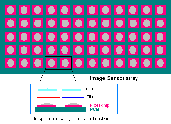
  3. CMOS is less sensitive and they always have transistor amplifier with each pixel. In CCD there is no requirement of transistor amplifier so more pixel area is devoted to sensitive area. (refer Figure)
  4. CMOS sensors can be fabricated on a normal silicon production line that is used to fabricate microprocessor and memories. CCD needs a dedicated production line.
  5. CMOS have the problem of Electrostatic discharge.
Three chip camera is made up of convex lens, beam splitter and red, green, blue sensor. Convex lens is used to focus the incoming light into the camera. The beam splitter is used to separate the color optically. It is made of glass prism and connected by red and blue dichroic reflectors. Proportional to light falls on the sensor, current is produced. It is then A-to-D converted and either stored are data is sent via cable.

       Bottom most layer on image sensor array is Printed Circuit Board (PCB). On the top of it pixel chips are mounted. Over that light sensitive sensor is placed (not indicated in the figure, light gray convex shape). Please note entire pixel chip is not devoted to sensor. The incoming light from dichoric reflectors are focused on each pixel chip by a lens. If it is a single chip camera then a primary color filter is placed in-between lens and sensor's sensitive area.

Single chip camera is made up of convex lens, color filter and sensor. Color filter will allow any one primary color (red, green, blue) to the sensor.  In a sensor array half of the array will have green filter and remaining half is equally split between red and blue. If color filters are arranged sequentially then aliasing effect will come into picture and results in MoirĂ© pattern. Films are made up of very small and very high irregular silver grains. This helps to suppress appearance of regular patterns. It is not possible to create a truly random pattern in single chip camera pixels. To create the effect of randomness pixels rows are arranged in such a way that each pixel row has different distribution compared to below and above row. This technique is called Bayer pattern and it was developed by Kodak company. When the pixels count and sampling rate are higher than any pattern frequency likely to appear (example checked shirt) then sequential filtering can be applied. For example Panavision Genesis has 12.4 million pixels. In sequential filtering each column contains one primary colour only.

DTV reception
Digital TVs are made to receive DTV broadcast signals. Set-top-box is external tuner system that can receive DTV signals and feed old analog television with analog signals. Color TV took 10 years to achieve five percentage market penetration. DTV in seven years achieved 20 percentage market penetration. Most of the satellite broadcast is in digital format and set-top-box in the receiver end generates analog signals which is suited to analog TVs. Days are not far off to have digital TV all over the world.

Source
  1. Chuck Gloman and Mark J. Pestacore, “Working with HDV : shoot, edit, and deliver your high definition video,” Focal press, 2007, ISBN 978-0-240-80888-8.
  2. Paul Wheeler, “High Definition Cinematography,” Focal Press, Second edition 2007. ISBN: 978-0-2405-2036-0
  3. http://www.scottpeter.pwp.blueyonder.co.uk/new_page_11.htm
  4. http://www.scottpeter.pwp.blueyonder.co.uk/Vintagetech.htm

Monday, 31 December 2012

Video Compression Basics

In olden days video transmission and storage was in analog domain. Popular analog transmission standards were NTSC, PAL and SECAM. Video tapes were used as a storage media and VHS and Betamax standards were adopted. Later video transmission and storage moved towards digital domain. Digital signals are immune to noise and power requirement to transmit is less compared to analog signals. But they require more bandwidth to transmit them.  In communication engineering Power and Bandwidth are scarce commodities.  Compression technique is employed to reduce bandwidth requirement by removing the redundancy present in the digital signals. From mathematical point of view it decorrelates the data. Following case study will highlight the need for compression. One second digitized NTSC video requires data rate of 165 Mbits/sec. A 90 minute uncompressed NTSC video will generate 110 Giga bytes. [1]. Around 23 DVDs are required to hold this huge data. But one would have come across DVD’s that contain four 90 minute movies. This is possible because of efficient video compression techniques only.

Television (TV) signals are combination of video, audio and synchronization signals. General public when they refer video they actually mean TV signals. In technical literature TV signals and video are different. If 30 still images (Assume each image is slightly different from next image) are shown within a second then it will create an illusion of motion in the eyes of observer. This phenomenon is called 'persistance of vision’. In video technology still image is called as frame. Eight frames are sufficient to show illusion of motion but 24 frames are required to create a smooth motion as in movies.

Figure 1 Two adjacent frames   (Top)  Temporal redundancy removed  image (Bottom)

Compression can be classified into two broad categories. One is transform coding and another one is statistical coding. In transform coding Discrete Cosine Transform (DCT) and Wavelet Transforms are extensively used in image and video compression. In source coding Huffman coding and Arithmatic coding are extensively used. First transform coding will be applied on digital video signals. Then source coding will be applied on coefficients of transform coded signal. This strategy is common to image and video signals. For further details read [2].

In video compression Intra-frame coding and Inter-frame coding is employed. Intra-frame coding is similar to JPEG coding. Inter-frame coding exploits the redundancy present among adjacent frames. Five to fifteen frames will form Group of Pictures (GOP).  In the figure GOP size is seven and it contains one Intra (I) frame and two Prediction (P) frame and four Bi-directional Prediction (B) frames. In  I frame  spatial redundancy alone  is exploited and it very similar to JPEG compression. In P and B frames both spatial and temporal (time) redundancy is removed. In the figure 1, Temporal redundancy removed image can be seen. In the figure 2, P frames are present in 4th and 7th position. Fourth position P1 frame contains difference between Ith frame and 4th frame. The difference or prediction error is only coded. To regenerate 4th frame, I frame and P1 frame is required.  Like wise 2nd frame uses prediction error between I, P1, and B1 frames. The decoding sequence is I PPBBBB4. (Check with a book)

Figure 2 Group of Pictures (GOP)

One may wonder why GOP is limited to 15 frames. We know presence of more number of P and B frames results in much efficient compression. The flip side is if there is an error in I frame then dependant P and B frames cannot be decoded properly. This results in partially decoded still image (i.e. I frame) shown to viewer for the entire duration of GOP. For 15 frames one may experience still image for half a second. Beyond this duration viewer will be annoyed to look at still image. Increase in GOP frame size increases decoding time. This time will be included in latency calculation. Real-time systems require very minimum latency.

In typical soap opera TV episodes very low scene changes occur within a fixed duration. Let us take two adjacent frames. Objects (like face, car etc) in the first frame would have slightly moved in the second frame. If we know direction and quantum of motion then we can move the first frame objects accordingly to recreate second frame. Idea is simple to comprehend but implementation is very taxing.  Each frame will be divided into number of macroblocks. Each macroblock will contain 16x16 pixels (in JPEG 8x8 pixels are called Block that is why 16x16 pixels are called Macroblock). Choose macroblock one by one in the current frame (in our example, 2nd frame in Figure 1) and find ‘best matching’ macroblock in the reference frame (i.e. first frame in Figure 2). The difference between the best matching macroblock and chosen macroblock is called as motion compensation. The positional difference between two blocks is represented by motion vector. This process of searching best matching macroblock is called as motion estimation [3].


Figure 3 Motion Vector and Macroblocks

       
         A closer look at the first and second frame in the figure 1 will offer following inferences. (1) There is a slight colour difference between first and second frame (2) The pixel located at 3,3 is the first frame is the 0,0 th pixel in the second frame. 
         In figure 3 a small portion of frame is taken and macroblocks are shown. In that there are 16 macroblocks in four rows and four columns.

Group of macroblocks are combined together to form a Slice.

Further Information:  
  • Display systems like TV, Computer Monitor incorporates Additive colour mixing concept. Primary colours are Red, Green and Blue. In printing Subractive colour mixing concept is used and the primary colours are Cyan, Magenta, Yellow and Black (CMYK). 
  • Human eye is more sensitive to brightness variation than colour variation. To exploit this feature YCbCr model is used. Y-> Luminance Cb -> Crominance Blue Cr-> Crominance Red. Please note Crominance Red  ≠  Red
  • To conserve bandwidth analog TV systems uses Vestigial Sideband Modulation a variant of Amplitude Modulation (AM) and incorporate Interlaced Scanning method.

Note: This article is written to make the reader to get some idea about video compression within a short span of time. Article is carefully written but guarantee cannot be given for accuracy. So, please read books and understand the concepts in proper manner.
Sources:
[2]  Salent-Compression-Report.pdf, http://www.salent.co.uk/downloads/Salent-Compression-Report.pdf  (PDF, 1921 KB)
[3]  Iain E. G. Richardson, “H.264 and MPEG-4 Video Compression Video Coding for Next-generation Multimedia,” John Wiley & Sons Ltd, 2003. (Examples are very good.  ISBN 0-470-84837-5)