Monday, 29 April 2013

Digital Cinema – Film vs. Digital Print


       We all know that movies are very powerful in terms of financial strength and the impact it has on the society. This multi-billion dollar industry started blossoming in 19th century. If ‘talking cinema’ (i.e. visual with audio) is taken as birth of cinema then it was in the year 1927. The name of the movie is  The Jazz Singer [1]. Nearly for a century movies were shot on film and it was developed with photo-chemical process. Projectors were used to rotate the film reels in a constant speed in front of a powerful lamp. The images created were projected on to a silver screen. People sitting on the dark enclosure were amused with the pictures shown. At the end of 20th century speech, audio, image and video were digitized. Slowly the ‘digital wave’ started engulfing the film technology. In this post, we will have a comparison between film and digital content.

The stakeholders of film are Actors, Technicians, Producer, Distributors, Exhibitors (Theatre) and Audience. One has to know the way movies are produced and role of each stakeholder in movie making process to understand the necessity for digital migration. Director of the movie makes the film on behalf of the Producer. So the right of movie lies with producer or Production Company. Region wise distributors are selected based on bidding and right to screen awarded to them for few weeks. Distributors in turn make contract with exhibitors to release the film in their region.

Movie making is made up of three stages: Pre-production, Shooting and Post production. Pre-production stage deals with story selection, screenplay and actor selection and signing contract with them [4]. Shooting is where movie scenes are shot with actors in various locations. It is a very time consuming process. A scene that lasts for minute in movie, Indian directors spends at least a day. Post production is much more time consuming process. Here raw footage that is shot in various locations is processed and arranged into a feature film.

Every day after shooting today’s footage is readied in the Lab for filmmakers to view. This is called dailies and in outside US it is called ‘rushes’. This acts as a feedback for director and camera man. In the Lab, raw footage is made into negative. Then they perform colour correction on negative but it is called as timing. Negatives are rearranged and if required cropped by director with the help of editor. This process is called as editing. Most of the time visual effects (VFX) scenes are added to make the movie worth watching. Actors jumping from 10th floor and other heroic stunts are possible due to VFX only. Then sound is processed and converted into optical signals and stored in twp sides of the film. Cropped and selected negatives are called ‘Cut Negative’. From the cut negative, ‘Answer Print’ is produced. Around 3000 release prints are developed from answer prints for world wide release. Regional movies will have at maximum 400 prints [4].

Star Wars Episode II : Attack on the Clones was the first
 movie fully shot  on  digital camera.  It was in the  year 2002.

Pros of Digital print
  • Cost of 35mm film print is around €1,500 but the cost digital print that is stored in computer hard disk is only €150 [3]. The cost reduction is substantial when the number of release prints is high.  This forces producer and distributor to embrace digital print.
  • Unlike film, making a new copy of digital release print is easy and economical. This feature makes piracy market to thrive well. To combat this encryption techniques are extensively used.
  • After several screening, film prints gets into wear and tear. In old film prints lot of scratches will be visible and it will annoy the viewers. This will not occur in digital print.
  • Proliferation of TV and DVD on homes started reducing movie goers. To retain the flock directors were forced to make visually stunning shots. When these shots are seen on a standard definition television (simply old CRT TV) they are not impressive. This forces audience to throng movie halls. Nowadays lot of Computer Generated Imagery (CGI) used in VFX. The best example is Steven Spielberg’s Jurassic Park. By nature CGI is digital.
  • Proliferation of Non linear editing. Earlier days at the time of editing negatives physically cut and spliced together.  In TV production they use few video players that are loaded with same raw footage. The first cut will be played from one player and second cut from another player and so on.  To change a cut one has to just change video players start and stop time. This helped making changes easy and after finalization cuts were copied into new video cassette.  As the process is non-destructive, original negative is preserved well. Slowly this technique was adopted by movie industry. If the negative is in digital form then it will much easier to perform on a computer.
  • Post production process time can be reduced considerably if film makers work on digital format. The level flexibility digital offers are really high. 
Pros of film print
  • Film is a proven and mature medium. 
  • Film equipment availability is not an issue and they are economical.  
  • 35 mm film is accepted as a movie standard worldwide. We have 16 mm, 8 mm formats also.
  • Even today, a century old 35 mm film stock can be projected on a silver screen any where in the world with the existing projectors. This is amazing when we consider the fact that two decade old software files are nearly unreadable. Thus the information is lost altogether.  
  • Huge amount of film stock is available as archives. So equipment's like projectors should be made available to protect and preserve the archives. Conversion of film archive into digital format and indexing the digital prints is tedious and capital intensive.
  • Raw footages are scanned and made into digital format called  Digital Intermediate (DI). All the post production process is carried out on DI and at last release print is made in film. This technique combines the benefits of digital format and robustness of film. 
  • Film projectors are cheap compared to digital projectors. If there is malfunctioning of film projector then either projector operator or local mechanic are capable to rectify them.  In digital projector company service technician has to arrive and rectify the malfunction.
  • 35 mm has more dynamic range, colour gamut compared to digital print. Analog projectors can project colour films with density range 5.0 which is equivalent to 17 stops [5]. Digital projector yet to arrive to match this feat.
  • Film does not have the problem of defective sensor or thermal noise problem. This problem in digital media arises because of underlying technology (CMOS or CCD) they employ.
All the points supporting film is taken from [1].  One will conclude the fight between film and digital is really tough. But the day will come when digital print reign supreme.

References 
  1. Brian McKernan, Digital Cinema, The revolution in Cinematography, post production and distribution, McGraw Hill, 2005.
  2. Charles S. Swartz (Editor), Understanding Digital Cinema : A Professional Handbook, Focal Press, 2004. (ISBN: 978-02408-06174) 
  3. Digital Cinema in Ireland, A review of possibilities, http://www.irishfilmboard.ie/files/reports/Digital_Cinema_in_Ireland.pdf, (PDF, 1510 KB)
  4. Private discussion with an VFX expert working in Prism & Pixels VFX Studio, http://www.prismnpixels.com
  5. Archives and digital cinema, http://ec.europa.eu/avpolicy/docs/reg/cinema/june09/archives_dcine.pdf (PDF, 361 KB).

Three Musketeers - Appendix

Earlier post dwelt on aperture, ISO and shutter speed. After posting it, I got following website.


Figure 1. Various aperture size
I failed in earlier post, to put a picture like above. I hope figure 1, makes easier to visualize aperture size. I have searched lot of webpages regarding shutter speed, ISO and aperture size. All the webpages give theory and at  maximum they may provide few images. But in this website they allow the user to interact with the images and get a FEEL about  shutter speed.  In figure 2 they provide three options Slow, Medium and Fast. User can select any one and find the corresponding result. Lot of examples like this. Please visit.

Figure 2.  Shutter speed with three options. Here Slow and Fast option is selected


Thursday, 28 March 2013

Three Musketeers - Aperture, Shutter Speed and ISO


        Today everyone is having a mobile camera and able to take a picture with single click. The memorable event that is captured in digital form most often are dull, blurred, overexposed or low in contrast. There is a wide gap between what was seen and what is available as image [1].

       To master the art of photography one should understand the elements of science of photography. One needs lot of practice and patience to master an art. Digital technology merely makes picture acquisition, storage and transmission processes much simpler and economical than earlier film technology. Knowledge on technology will help to work with modern camera with ease.  Access to modern digital camera with its all fancy features does not guarantee a good photograph. Taking snap of beautiful females (in photography they are called subjects) does not guarantee a beautiful picture either.

       The simple fact is “Light falls on the subject and it is captured by the camera”.  With this “each photograph is expected to convey an emotion”. In this post let us know three important settings of digital camera that will help to acquire a picture properly. They are aperture, shutter speed and ISO.  These three form a golden triangle. By adjusting these controls one can produce beautiful pictures.

Aperture
        Aperture controls the light that falls on the lens. Aperture is circular in shape. Aperture adjustments are expressed in F-stops [2]. They are f/2, f/2.8,f/4, f/5.6, f/8, f/11, f/16, f/22 and f/32. The above list gives the various aperture ratios that are possible. The numerator ‘f’ stands focal length of lens and it is divided by a number.

Let lens focal length be  50 mm.
(i) f/2  => 50 mm / 2  => 25 mm (aperture diameter)
(ii) f/16=> 50 mm / 16=> 3.125 mm (aperture diameter)
(iii) f/32=> 50 mm / 32=> 1.563 mm (aperture diameter)

Moral of the example is bigger the denominator lesser the aperture diameter and in turn less light falls on into the lens. The denominator series do possess regularity. Aperture area of f/16 is 7.6 sq. mm, f/22 is 4.15 sq. mm and for f/32 is 1.9 sq. mm. As F-stop denominator increases by one step (say 16 to 22) aperture area doubles. Likewise, as F-stop denominator decreases by one step (say 32 to 22) aperture area halves.

In digital camera, if the aperture is set then automatically other things are adjusted in tandem to the aperture value.  The aperture settings used in cameras are calibrated in f/stops [1].

 Shutter
         It is a device that allows the light to fall on the lens for finite duration of time.  Mostly time will be in seconds. Unlike aperture, it has only two states Open and Close. It has following speeds 1, 1/2, 1/4, 1/8, 1/15, 1/30, 1/60, 1/125, 1/250, 1/500, 1/1000, 1/2000. Above speeds are called stops. Here also increase in stop means shutter speed is doubled and decrease in stop means shutter speed in halved. The basic question arises in every mind is what is need for variable shutter speed? This will be answered in following ISO section.

ISO
         Appropriate title for this section will be film sensitivity. In digital camera it should be sensor sensitivity. Typically it is represented as ISO 100 or ISO 200. In this sensitivity is represented in number format and prefix ISO and ASA denote the standard setting organization (like ISO, ASA and EI). These organizations specify film sensitivity in numbers. The ISO range is, as follows 25, 50, 100, 200, 400, and 800 up to 3200. Higher the ISO number means more it is sensitive to light. It indicates that less light is sufficient take a photograph. If a fruit bowl is photographed keeping shutter speed as 1/8”, F-stop as f/5.6 and ISO having 100 and 1600 values will result in darker fruit bowl image and brighter fruit bowl image. Refer [1] shows series of photographs to illustrate this concept very clearly.

A photograph is taken when sufficient light is not available to record details in the darker regions then it is called  underexposed. A photograph is taken when too much is light wash out details in brighter regions then it is called overexposed. Aperture size and shutter speed also can be adjusted to handle this situation. Various ISO numbered films are available to freeze the picture with available light .

The shutter speed and aperture size determines the amount of light sent into the lens. The ISO number indicates the amount of light required to freeze a picture properly.  If the ISO number is fixed then either shutter speed or aperture size can be varied to get a  correct exposure.

This will be explained with an example. Let
Aperture: f/11  
Shutter Speed: 1/250”
ISO: 100

If the aperture is reduced by a stop (f/8) then correspondingly shutter speed has to be increased by an F-stop (1/500”). Likewise if the aperture is increased by a stop (f/16) then shutter speed should be reduced by an F-stop (1/125”). Please refer [2] to find a exercise on this matter.
(f/11, 1/250”, 100) = (f/8, 1/500”, 100) = (f/16, 1/125”, 100)

Depth of field
        It is difficult to convey in words. Figure 1 shows billiards table and a railway over bridge. In the billiards ball image one infer that white ball is near and black ball, lamp shade and green screen are far away from the camera. Having a closer look reveals that only white ball is crisp while rest of the image that is very near to camera (say stick) as well as far away (say green screen) are very blurry. This type of images are called  shallow depth of field. In the railway over bridge image railway track that is near to the camera and last girder of the bridge that is far away from camera are equally crisp irrespective of the distance. This type of images are called deeper depth of field. Changing the size of the aperture has a bearing on depth of field. Larger aperture area creates a shallow depth of field and narrow depth of field creates deeper depth of field.

Image Courtesy : Reference 2

Creation of Motion
        The shutter speed is made slower than the motion of the subject and photograph is taken. These kinds of pictures create an illusion of motion. In figure 2 two darts are in board and another one is just arriving the board. This is very useful when taking photographs of athletes in action.
Image Courtesy: Reference 2

Note
I came across the Science Reporter magazine in a railway station. As it was only Rs. 20 (40 cents) I bought it. It is a wonderful magazine and worth the prize. It is published by Council of Scientific & Industrial Research (CSIR), Research Labs of govt. of India. (http://www.niscair.res.in/sciencecommunication/Popularization%20of%20Science/scirep0.asp). In that I studied Ref. [1] and it was nice. Later I studied few books on photography in the library. Armed with knowledge I searched  in Google and I found out Ref. [2]. It is a 40 page document and it worth studying the document fully. The document contains very nice illustrations, less theory, exercise and top of all answers to exercise questions.

References

  1. Somya Maitra, “Playing with Photons – Clicking the ‘Right’ Photograph”, Science Reporter, Vol. 50, No. 3, March 2013, pp. 8–13, ISSN 0036-8512.
  2. John M. Setzler Jr., “Expoure”. http://www.shutterfreaks.com/Tips/Exposure/exposure111.pdf    (PDF, 1375 KB)

Wednesday, 27 February 2013

Digital Television

         In New York World’s Fair, first time public had a chance to see Television.This happened in the year 1939. It took two years to develop a standard for Black and White TV broadcast. In USA Color TV broadcast standard was developed by National Television Systems Committee (NTSC) in 1953. It has 525 horizontal scanning lines out of which 480 lines are active (it means visible). Interlaced scanning is used. This system is called Standard Definition TV (SDTV) and mentioned in technical literature as 480i (480 lines and interlaced scanning) [1]. Early TVs were developed by Marconi company and John Logie Baird of England. Marconi company developed interlaced scanning and Baird used progressive scanning. Marconi used landscape format (width is longer and height is short) but Baird used portrait format to suit talking head. British Broadcasting Company (later it became corporation) adopted Marconi company system [2]. For early TV photos are available in Internet [3], [4].

Digital Television
         Federal Communications Commission (FCC) of USA established Advanced Television Systems Committee (ATSC) in 1995 to form Digital Television (DTV) standards. In 1996 DTV standard was adopted in USA. This standard was adopted by Canada, South Korea, Argentina and Mexico. As per original plan of FCC no analog broadcast after February 2009 in USA.

HDTV
One of the variant of DTV is High Definition Television (HDTV). ATSC proposed 18 different DTV formats out of which 12 are SDTV formats and remaining are in HDTV format. A DTV to be qualified as a HDTV should satisfy following five parameters. They are

  • Number of active lines per frame (≥720), 
  • Active pixels per line (≥1280), 
  • Aspect ratio (16:9), 
  • Frame rate (≤30), exception permitted
  • Pixel shape (square).

         Please note DTV with aspect ratio of 16:9 and frame size of 480x704 is available. But it is not HDTV format as it not having required active lines per frame.

  The six variant of HDTV format can be broadly classified into two groups based on frame size. First group has 1080x1920 frame size with 24p, 30p (progressive) and 30i (interlaced) frames per second (fps). Second group has 720x1280 frame size with 24p, 30p, 60p fps. Square pixels are widely used in computer screens. Progressive scanning is suitable for slow moving objects and interlaced scanning is suited for fast paced sequences. Minimum 60 frames per seconds are required to compensate its deficiency. DTV is designed to handle 19.39 Mbps only. This bit rate is not sufficient to handle 1080p with 60 fps. DTV’s SDTV formats can be broadly classified into three categories. First one is with 480x640 frame size, 4:3 aspect ratio, square pixel and with 24p, 30p, 30i and 60p fps. This is very similar to the existing analog SDTV format. Remaining two uses 480x704 frame size.

HDTV camcorder
HDTV camcorders were introduced in 2003. A professional camera recorder (camcorder) will have 2/3” inch image sensor with 3 chips, color view finder, and 10x or more zoom lens. In professional camcorders cables connectors are provided in the rear of the camera. The interface standards are IEEE Firewire or High Definition Serial Digital Interface (HDSDI). Coaxial cables are connected and content is sent to monitor or a Video Tape recorder.

      A consumer grade camcorder uses 1/6” inch image sensor with single chip and 3.5” LCD screen to view. It weighs around a kg and cost is less. Recorded content will be stored video cassette or hard disk.
Professional camera like Dalsa origin has an image sensor array of 4096 x 2048. At a rate of 24 fps it generates 420MB/second [2, pg. 165]. It means that a CD will be filled with 90 seconds of data. Image sensor array made up N x M pixels. These pixels may be made up of Charge Coupled Device (CCD) or Complementary Metal Oxide Semiconductor (CMOS).  Consumer grade camcorders and Digital camera use CMOS pixels. Following section will compare CCD and CMOS [2].
  1. CMOS releases less heat and consume 100 times less power than CCD.
  2.  CMOS can work well with low light conditions.
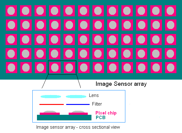
  3. CMOS is less sensitive and they always have transistor amplifier with each pixel. In CCD there is no requirement of transistor amplifier so more pixel area is devoted to sensitive area. (refer Figure)
  4. CMOS sensors can be fabricated on a normal silicon production line that is used to fabricate microprocessor and memories. CCD needs a dedicated production line.
  5. CMOS have the problem of Electrostatic discharge.
Three chip camera is made up of convex lens, beam splitter and red, green, blue sensor. Convex lens is used to focus the incoming light into the camera. The beam splitter is used to separate the color optically. It is made of glass prism and connected by red and blue dichroic reflectors. Proportional to light falls on the sensor, current is produced. It is then A-to-D converted and either stored are data is sent via cable.

       Bottom most layer on image sensor array is Printed Circuit Board (PCB). On the top of it pixel chips are mounted. Over that light sensitive sensor is placed (not indicated in the figure, light gray convex shape). Please note entire pixel chip is not devoted to sensor. The incoming light from dichoric reflectors are focused on each pixel chip by a lens. If it is a single chip camera then a primary color filter is placed in-between lens and sensor's sensitive area.

Single chip camera is made up of convex lens, color filter and sensor. Color filter will allow any one primary color (red, green, blue) to the sensor.  In a sensor array half of the array will have green filter and remaining half is equally split between red and blue. If color filters are arranged sequentially then aliasing effect will come into picture and results in MoirĂ© pattern. Films are made up of very small and very high irregular silver grains. This helps to suppress appearance of regular patterns. It is not possible to create a truly random pattern in single chip camera pixels. To create the effect of randomness pixels rows are arranged in such a way that each pixel row has different distribution compared to below and above row. This technique is called Bayer pattern and it was developed by Kodak company. When the pixels count and sampling rate are higher than any pattern frequency likely to appear (example checked shirt) then sequential filtering can be applied. For example Panavision Genesis has 12.4 million pixels. In sequential filtering each column contains one primary colour only.

DTV reception
Digital TVs are made to receive DTV broadcast signals. Set-top-box is external tuner system that can receive DTV signals and feed old analog television with analog signals. Color TV took 10 years to achieve five percentage market penetration. DTV in seven years achieved 20 percentage market penetration. Most of the satellite broadcast is in digital format and set-top-box in the receiver end generates analog signals which is suited to analog TVs. Days are not far off to have digital TV all over the world.

Source
  1. Chuck Gloman and Mark J. Pestacore, “Working with HDV : shoot, edit, and deliver your high definition video,” Focal press, 2007, ISBN 978-0-240-80888-8.
  2. Paul Wheeler, “High Definition Cinematography,” Focal Press, Second edition 2007. ISBN: 978-0-2405-2036-0
  3. http://www.scottpeter.pwp.blueyonder.co.uk/new_page_11.htm
  4. http://www.scottpeter.pwp.blueyonder.co.uk/Vintagetech.htm

Wednesday, 30 January 2013

Video Compression Standards


In the earlier post basics of digital video compression was discussed. In this post five broad application areas of video and H.26x and MPEG4 video compression standards will be discussed.
  In all cases video frames are acquired by camera, compressed and stored in a non-volatile memory. Based on the requirement compressed video is transmitted to other places. Quality of video depends upon following factors viz: Number of frames per second, frame resolution, pixel depth. A High Definition (HD) video exhibits 25 frames per second and each frame has 1920 x 1080 pixels.  A pixel consumes 24 bits to represent RGB values. Video quality has a direct bearing on cost. One has to understand the requirement first and based on that video quality has to be finalized to keep cost at minimum.

1. Studio:
In video and film production video taken in a set or location is called raw footage. Then footages are taken up editing. Here video processing operations like colour space conversion, noise reduction, motion compensation and frame rate conversion is carried out based on the requirement. After this Director and editor of the movie sit together and remove unwanted portions and then rearrange footage in an order to make a movie. At the time of editing there will be loss of quality. To compensate this raw footage should be of highest quality.

2. Television:
         Digital television signals are broadcasted through terrestrial transmitters or by satellite transponders. Digital Terrestrial broadcast is popular in USA and Europe. Digital video is economically stored and distributed through Video Compact Disc (VCD) and Digital Versatile Disc (DVD). In News clips frame-to-frame transition  will be less. In sports and action movies frame-to-frame transition will be high. Digital Video signals are optimized to standard resolution TVs ( old NTSC, PAL, SECAM). Earlier MPEG-1 video compression standard was used. Now MPEG-2 is used to get HD (HD720, HD1080) quality.

Figure 1.  Frame sizes used by different TV standards. 
3. Internet streaming:
 In video streaming continuous data is sent to the client over the Internet and the user is able to decode and view the video in near real-time. Internet is slowly becoming like a video server. YouTube, metacafe, dailymotion are few examples for popular video servers. The files used by servers are MOV, FLV, MPEG-4, 3GP and FLV.  It is called as wrappers and it contains meta-data. The video codec used are MPEG-4, H.264, Sorenson Spark, VC-1 etc [1].  The video resolution available is 240, 360 and HD. In streaming latency (time delay) is the greatest problem. The problem of latency is unheard in broadcast technologies. In video streaming server do not allow to store the content but on-line tools are available to store in local hard disk.

4. Video conferencing:
        The next great thing is video conferencing. It may be one-to-one or conference call. Foundation for video telephony started 40 years back. Integrated Services Digital Network (ISDN) technology was built to handle video telephony. A new compression standard H.261 was built. At that time video telephony was not commercially successful and stood as technological feat only. Advent of third generation (3G) wireless technologies recreated the interest in video telephony and conferencing. Video conference system has much more stringent latency considerations. Humans can tolerate loss in visual quality and not on latency. Now H.264 protocol is used widely. The video resolution will be 352 x288 i.e. one fourth size of PAL TV signals.

5. Surveillance:
     Fall in prices surveillance video systems and proven ability in crime prevention and crime detection made wider deployment. The video should be of high quality so as to able to recognize suspect face and the video content should not be altered. If it altered then it will not be accepted as proof in the court of law. They use Motion JPEG, H.264 and MPEG standards for recording surveillance video. Real-time monitoring systems use H.264 and MPEG video codecs and to capture frames Motion JPEG (MJPEG) codec are employed. Entertainment industry and surveillance industry requirements are totally different. Poor lighting, 24x7 storage requirement are unique to surveillance applications [2].

Video Compression standard interrelationships:

          There is a long list of video compression standards are available. Careful study of various standards will reveal lot of commonality among them. MPEG and H.26x  stands out as top contenders.

I. MPEG:
            Motion Pictures Experts Group (MPEG) is a study group that develops digital video standards for International Standards Organization (ISO) and International Electrotechnical Commission (IEC).  These standards were built for entertainment industry.  In 1993 MPEG-1 was introduced to store digital video with a quality equal to VHS tape. In 1994 MPEG-2 was developed to handle HD video. MPEG-3 was merged with MPEG-2. MPEG-4 was introduced in 1999 and it uses Wavelet transform instead of Discrete Cosine Transform (DCT). Variants like MPEG-7 and MPEG-21 are available [3],[4].

II. H.26x:
           International Telecommunications Union’s Telecommunication standards division was responsible to develop H.26x series of standards. These standards were built to handle video calls. In video calls the frame-to-frame transition will be less. Most of the time it has to transmit human face which moves mildly. This H.26x is network resilient and it has lowest latency. To reduce latency  ‘B’ frames will be avoided in the coded frames. As it evolved from telephone systems it uses 64k chunks. Here also DCT is used.
            Later H.262 was developed and  it is similar to MPEG-2. Then H.263 was developed. In 1999 developers of H.26x, Video Coding Experts Group (VCEG) joined with ISO/IEC to form Joint Video Team (JVT). They built H.264/MPEG-4 Part 10. This standard is otherwise called as Advanced Video Coding (AVC). In MPEG-4 there are 16 parts and 10th part discuss about video coding. The 4:2:0 sampling is used and both progressive and interlaced scanning is permitted.

III. Motion JPEG:
          It was developed in 1992. Here only intra-frame coding is used. Put it simply each frame is a JPEG image. It never uses inter-frame coding. Because of this compression efficiency is poor but it has relatively less latency and more resilient to errors. One may wonder how MJPEG different from JPEG. In MJPEG 16 JPEG frames are shown within a second to create an illusion of motion. It consumes more storage size but it contains more information. It frames can be used as proof in court of law. In MPEG systems it sends only two to four full frames (I-frames) per second to receiver. Now MJPEG2000 that is similar to JPEG2000 is introduced. It uses Wavelet transform instead of DCT. It is computationally tedious but compression efficiency is high. [4]

Source:
 [1] Yassine Bechqito, High Definition Video Streaming Using H.264 Video Compression, Master's Thesis, Helsinki Metropolia University of Applied Sciences. pg.18, 21(PDF, 3642 KB)
[2] http://www.initsys.net/attachments/Compression and DigitisationPDF.pdf (PDF, 242 KB)
[3] Iain E. G. Richardson, “H.264 and MPEG-4 Video Compression Video Coding for Next-generation Multimedia,” John Wiley & Sons Ltd, 2003. (Examples are very good.  ISBN 0-470-84837-5)
[4] Salent-Compression-Report.pdf,  http://www.salent.co.uk/downloads/Salent-Compression-Report.pdf  (PDF, 1921 KB)